3 minutes
Hacking buttons
Idea
You’d think when living far from the city centre and near the underground station, there’s plenty of parking space? Nothing could be further from the truth.
However, something is even more baffling. Most of the street at which I live is closed by a road barrier which could be opened using a remote control. There’s no point in using it though because past the barrier there’re even fewer free parking spaces.
Since I do not care about it working, let’s play with it using Arduino.
Progress
The project is based on a project from this kit - “15 HACKING BUTTONS create a master control for all your devices!”.
Remote control investigation
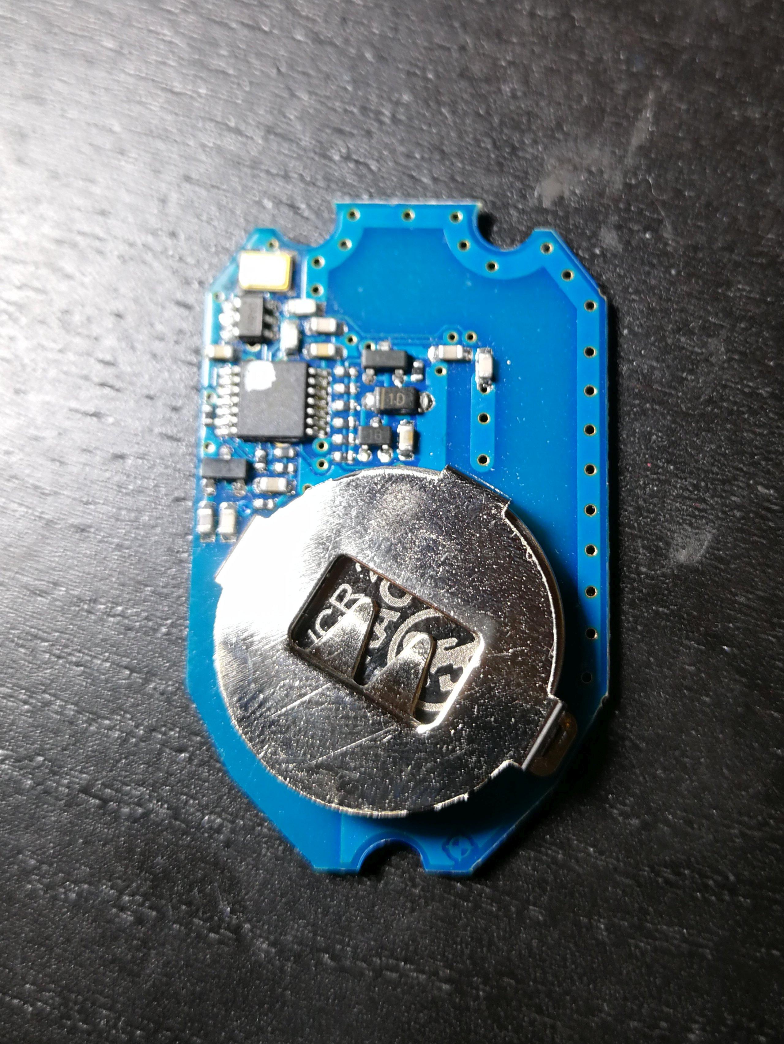
This is how the back of the opened remote control looks like. As you can see, there are no buttons here.
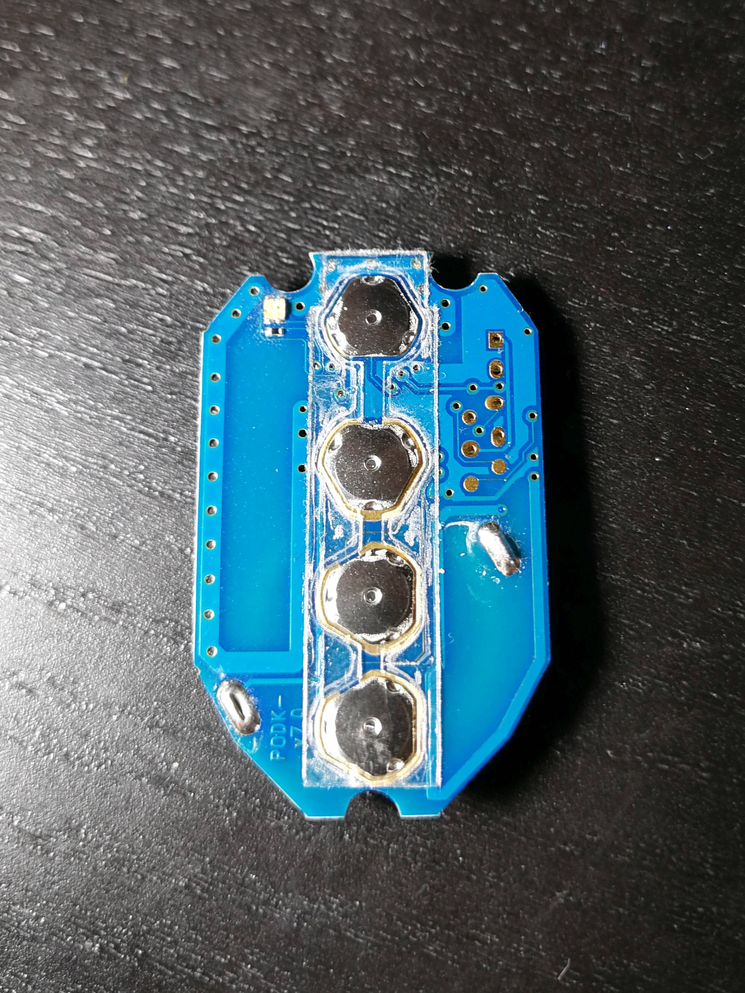
On the other side we can see the four buttons covered with some metal caps. In order to connect Arduino to each button we need to remove these.
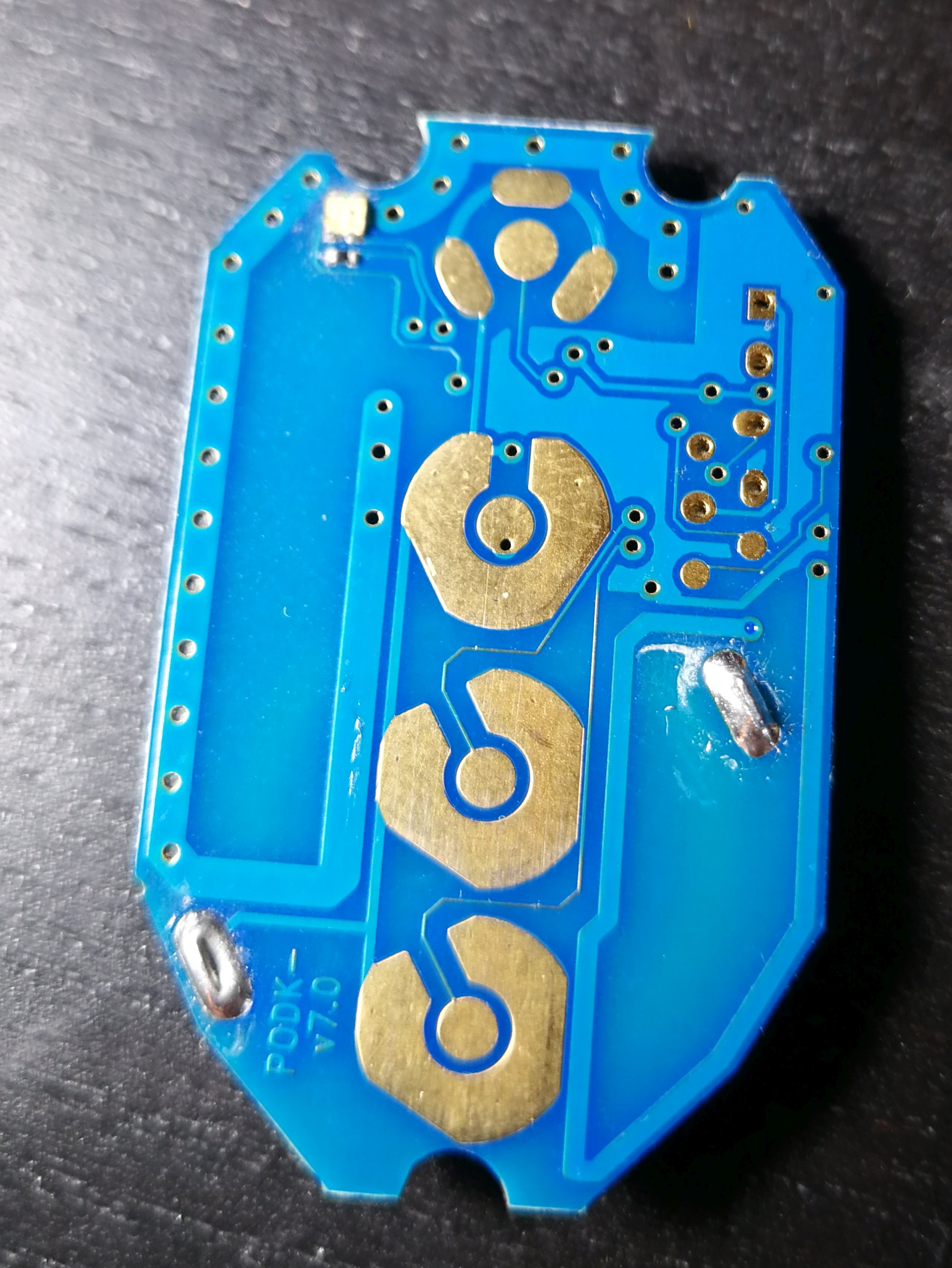
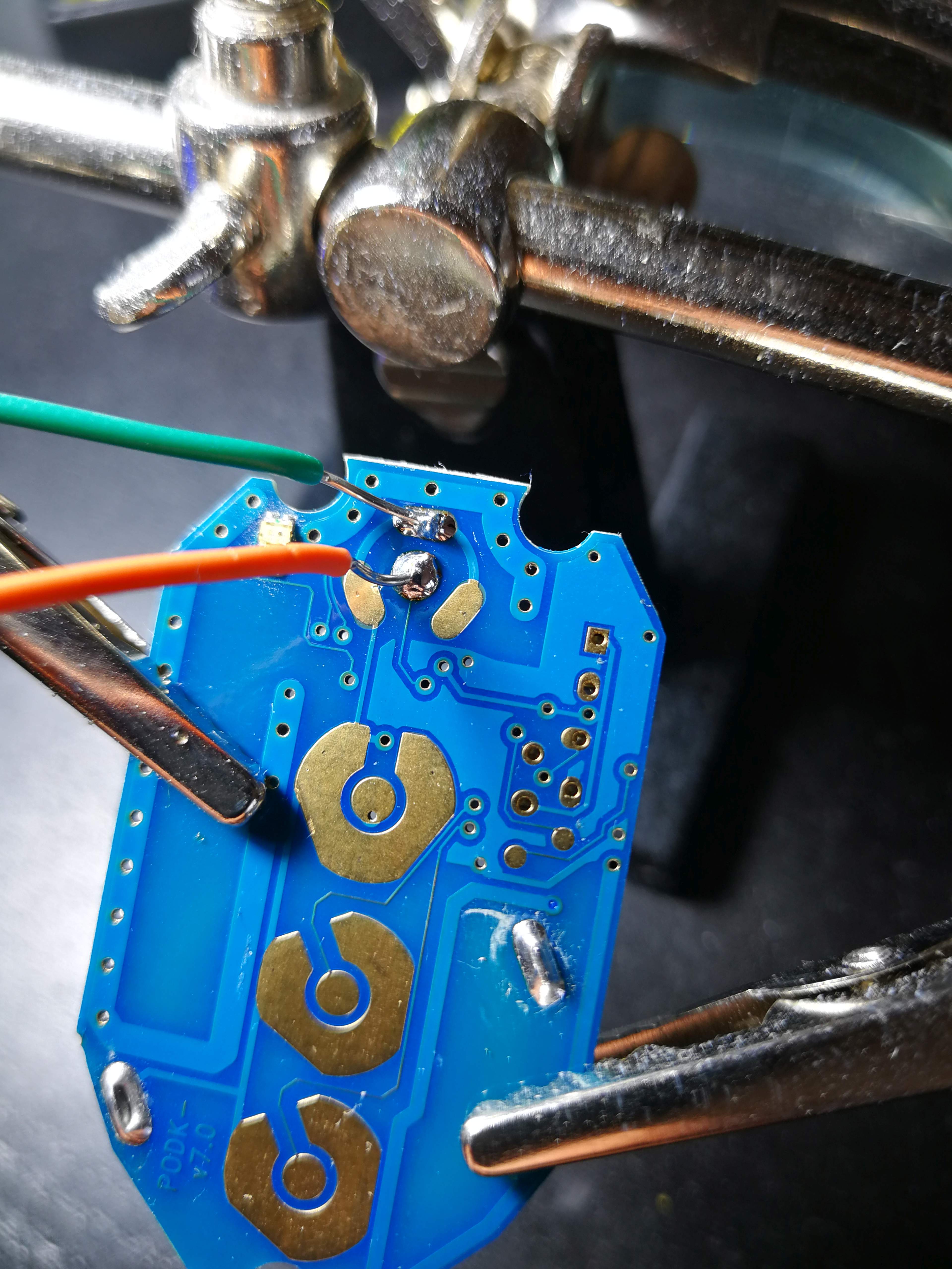
After removing the caps this is how the PCB[1] looks like.
Soldering
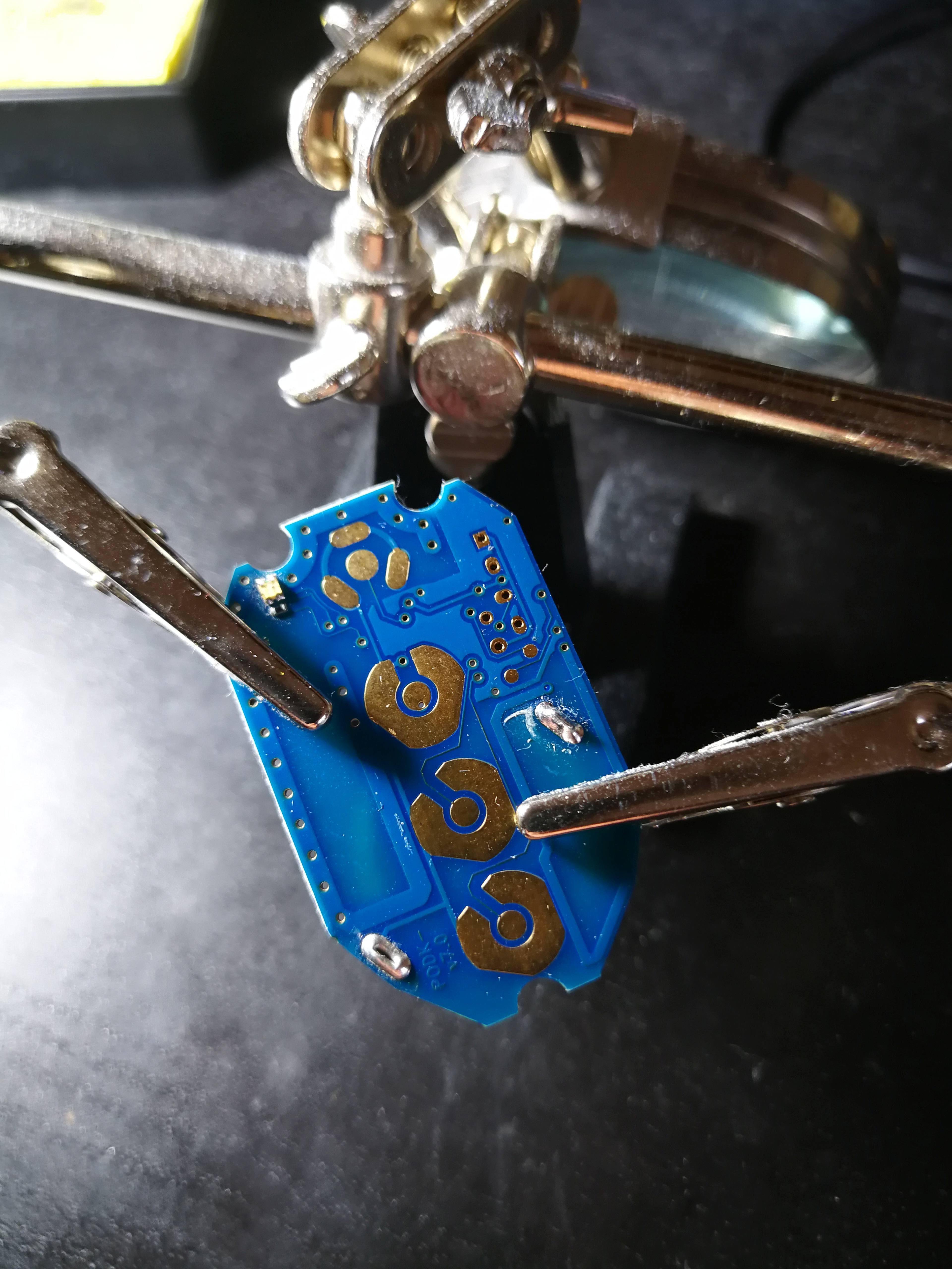
First step is to mount the remote control PCB[1] into the soldering arms.
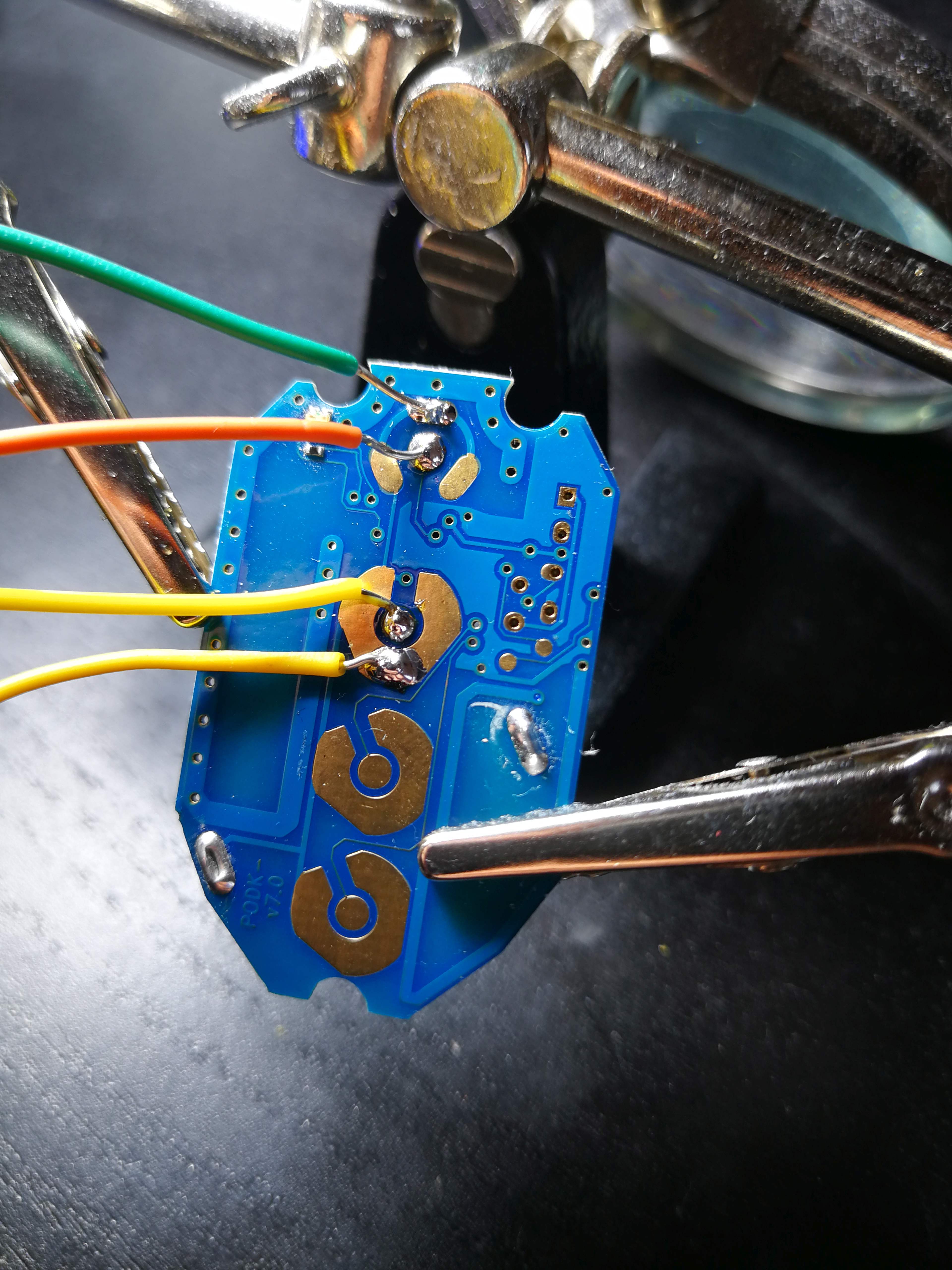
Two wires are soldered to the first button.
And the other two to the second button of the remote control.
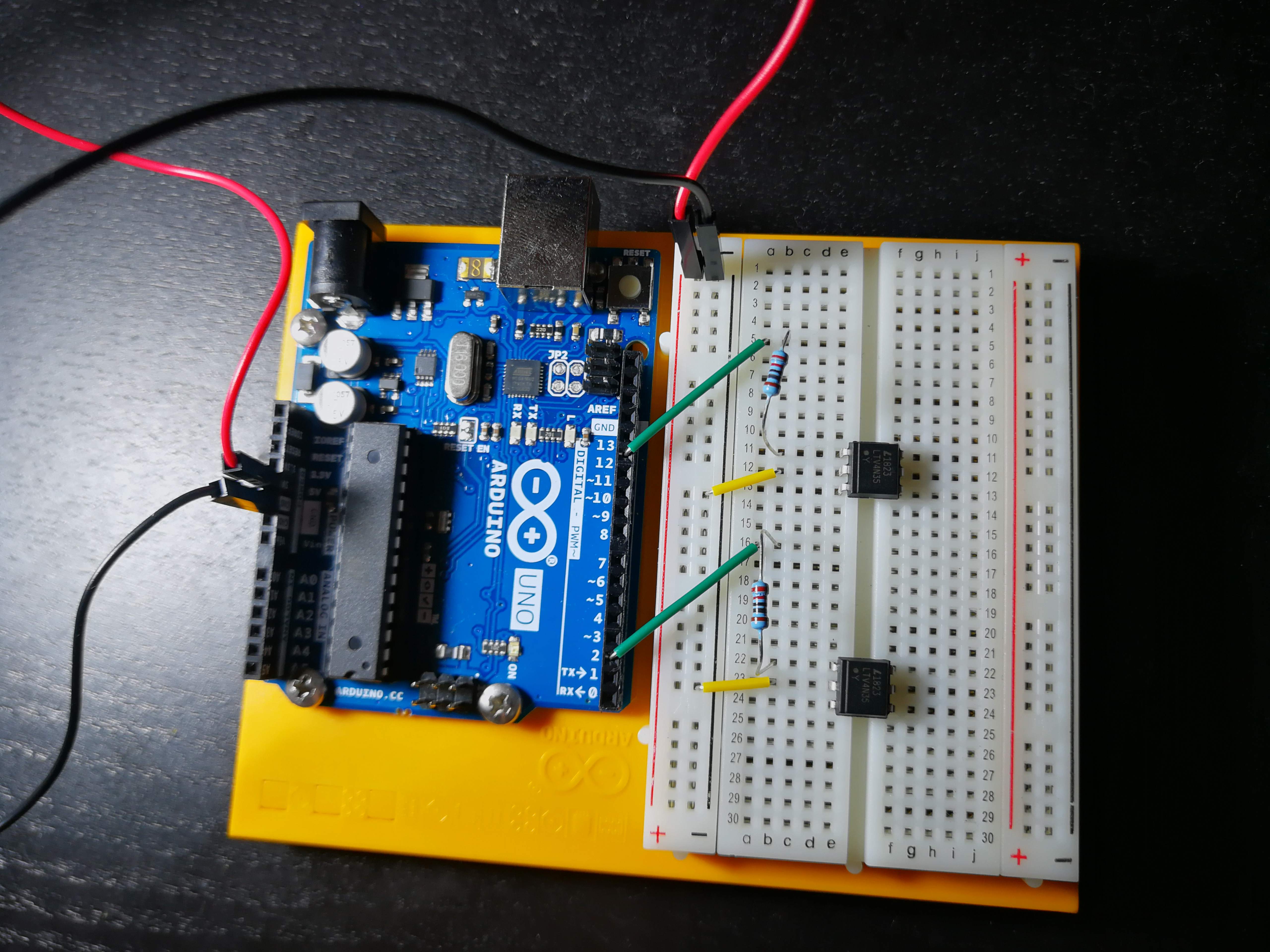
Assembling circuit
In order to control the remote control using Arduino I used something called an optocoupler.
Schematic of an optocoupler
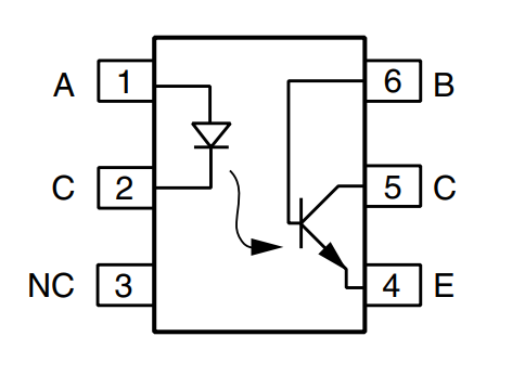
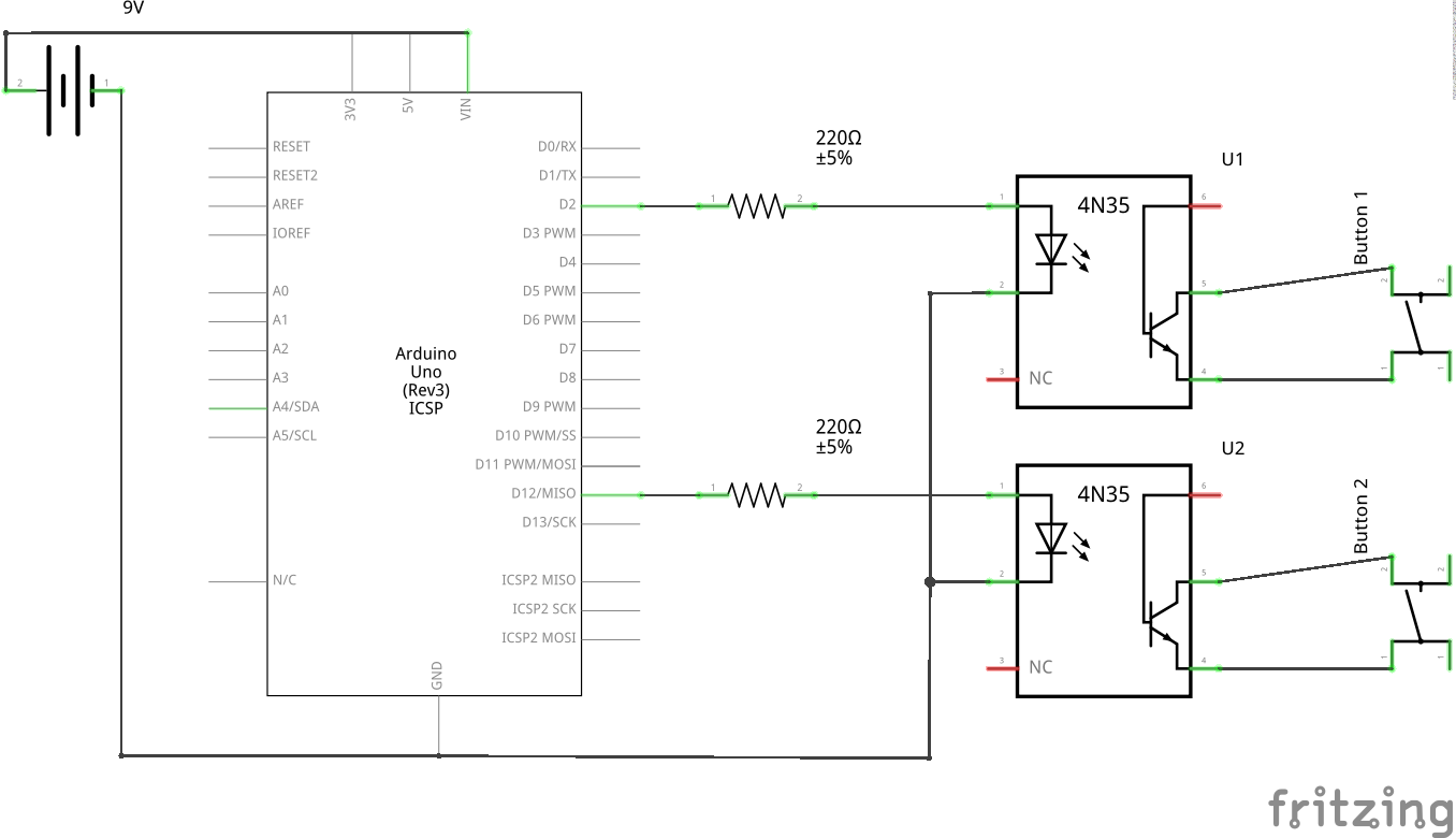
It is an IC[2] which allows controlling one circuit from a different one without any electrical connection between them. It consists of an LED[3] and a phototransistor[4]. When the LED[3] is powered by Arduino, the light detector closes the internal switch. The switch is connected to 4 and 5 pin (datasheet link). When the switch is closed, the two pins are connected. The two pins being connected is equivalent to the button being pressed in our case.
I also needed a 220 Ω resistor to not destroy the LED[3] inside the optocoupler.
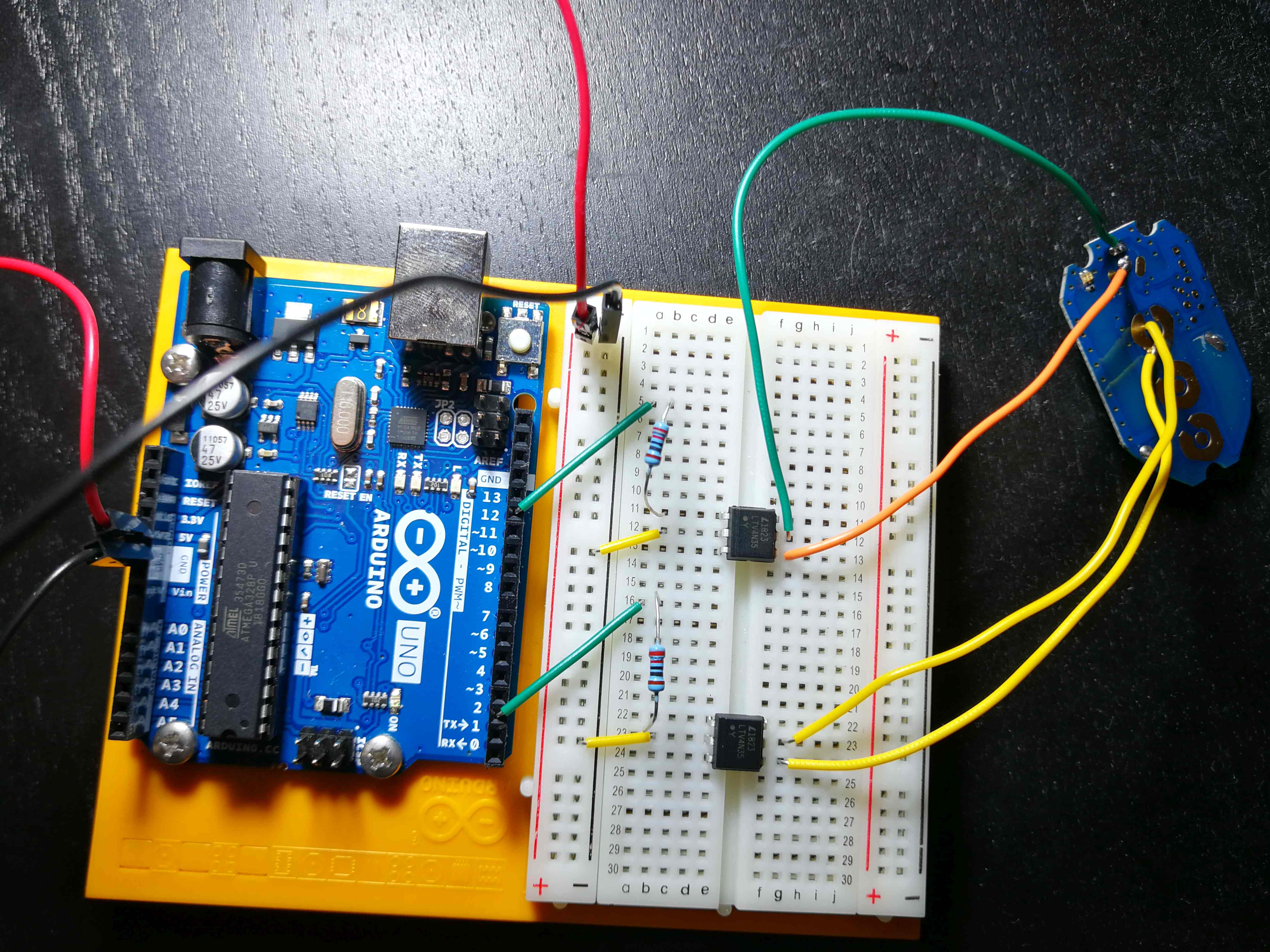
Arduino connected to the circuit
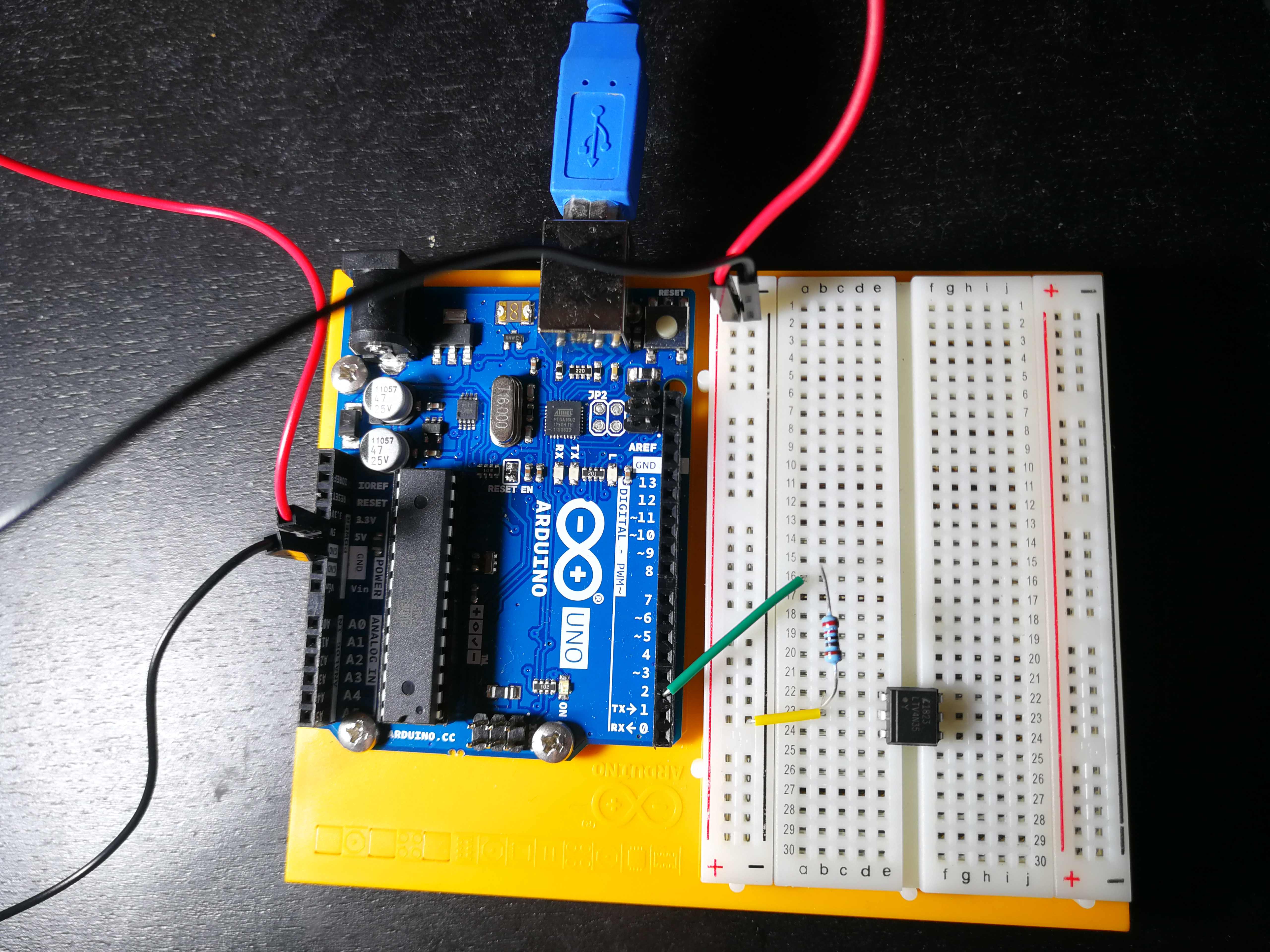
There are two buttons to control (two arms of the road barrier) so I duplicated what I already had.
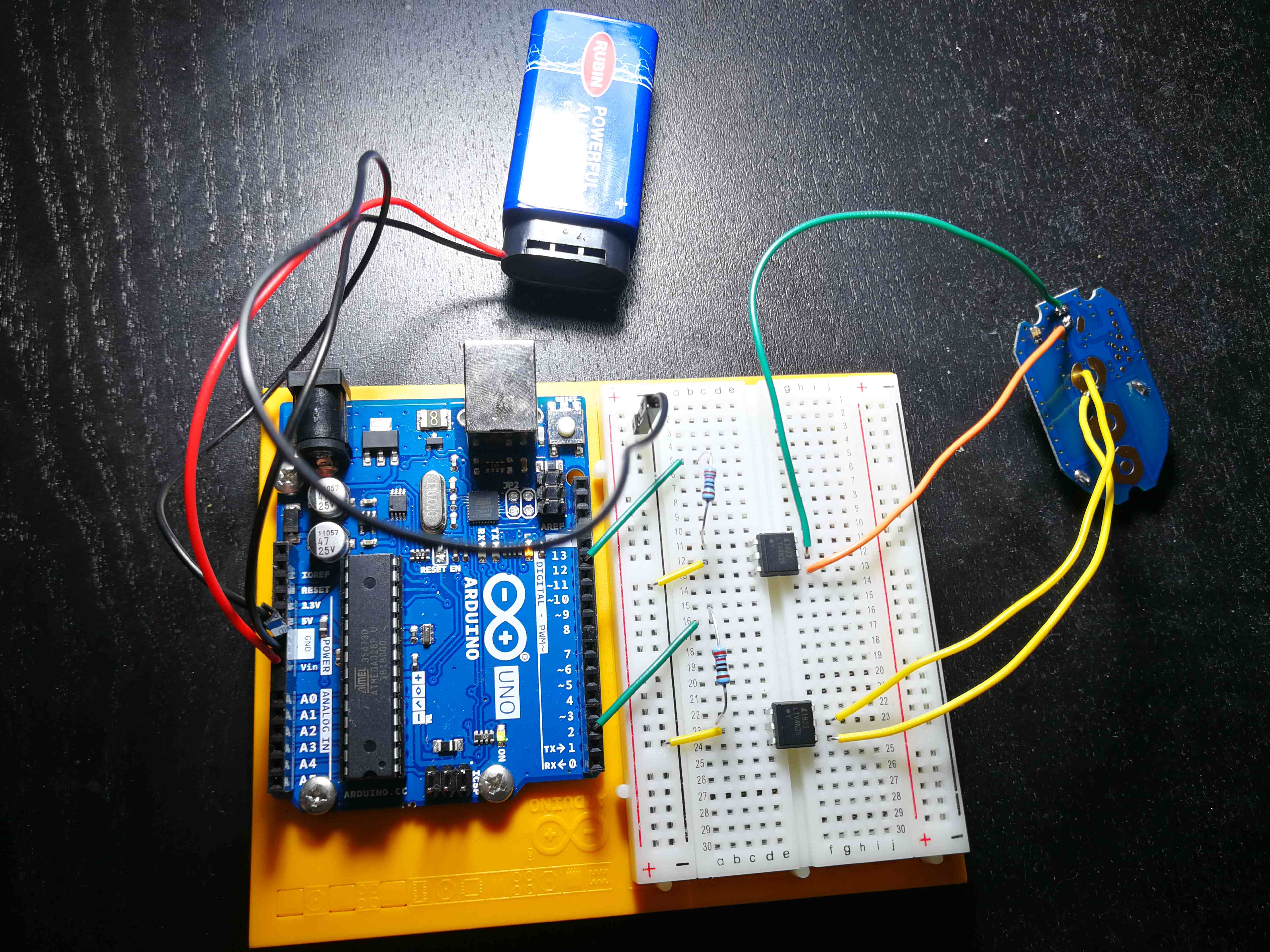
Arduino and the remote control connected.
9V battery is used to power the Arduino so it can be disconnected from the USB port.
Schematic of the circuit
Arduino source code
Code behind it is pretty straightforward.
In setup I set both of the pins connected to optocouplers to OUTPUT mode.
This mode allows the pins to provide current to the optocouplers.
In loop a random number is being chosen.
Depending on the parity, first or the second button is being pressed.
The pressButton function simulates pressing the button on the remote control.
Arduino sets pin voltage to 5V for 1000 ms (using delay function).
Then pin voltage is being set to 0V for a random duration (10 to 60 seconds).
There is source code below which is also available on my github here.
const int optoPin1 = 2;
const int optoPin2 = 12;

unsigned long seconds = 1000L;
unsigned long minutes = seconds * 60;
unsigned long hours = minutes * 60;

const int pressTime = 1000;

void setup(){
  pinMode(optoPin1, OUTPUT);
  pinMode(optoPin2, OUTPUT);
}

void loop(){
  int randomNumber = random(10, 60);

  if (randomNumber % 2 == 0)
    pressButton(optoPin1, randomNumber);
  else
    pressButton(optoPin2, randomNumber);
}

void pressButton(int pinNumber, int randomNumber){
  digitalWrite(pinNumber, HIGH);
  delay(pressTime);
  digitalWrite(pinNumber, LOW);

  delay(randomNumber * seconds);
}